
- Home
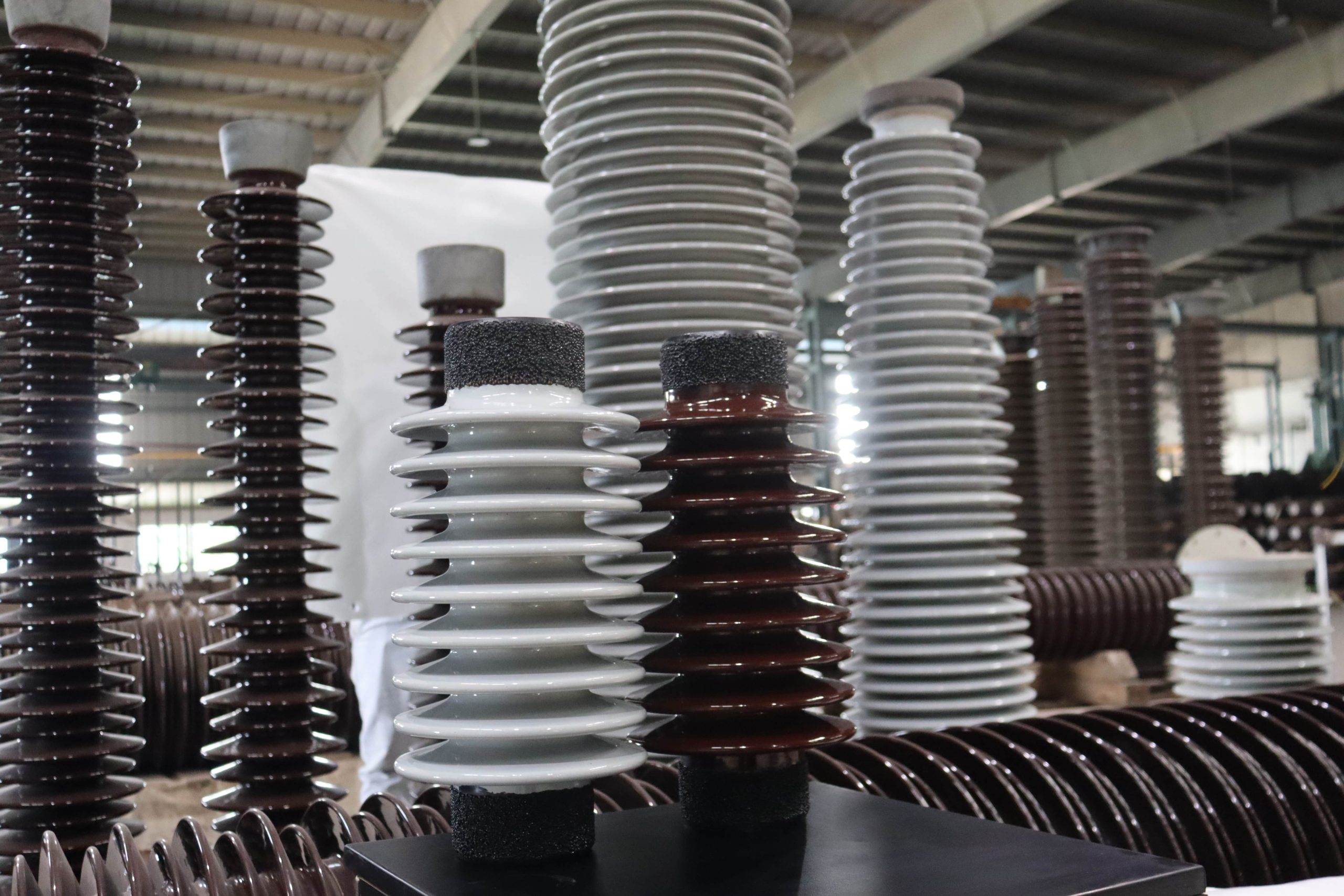
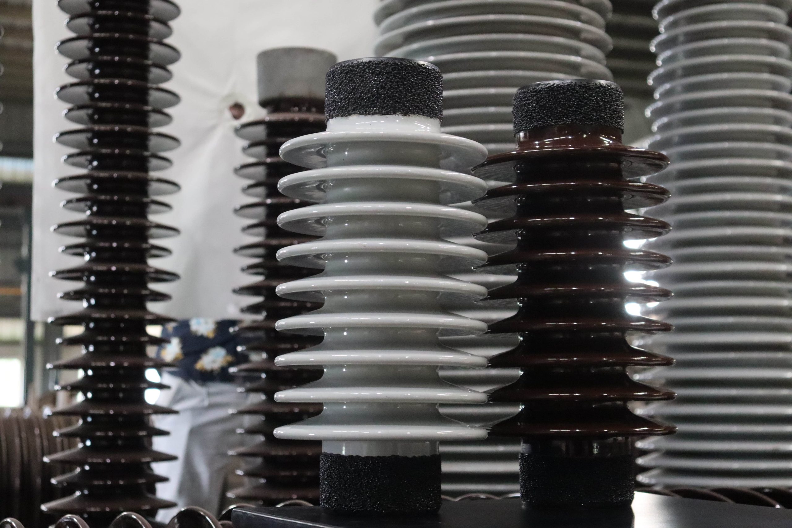
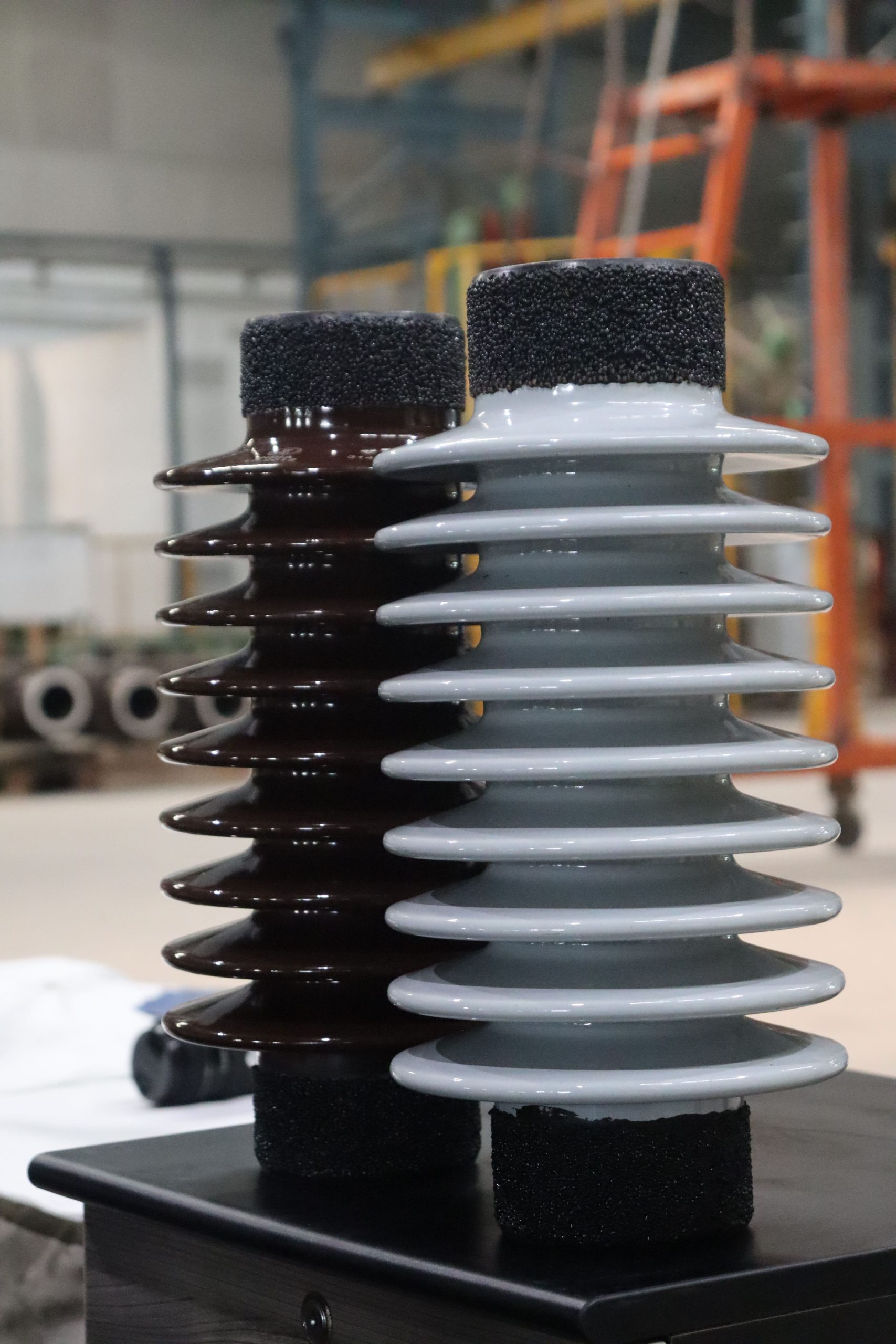
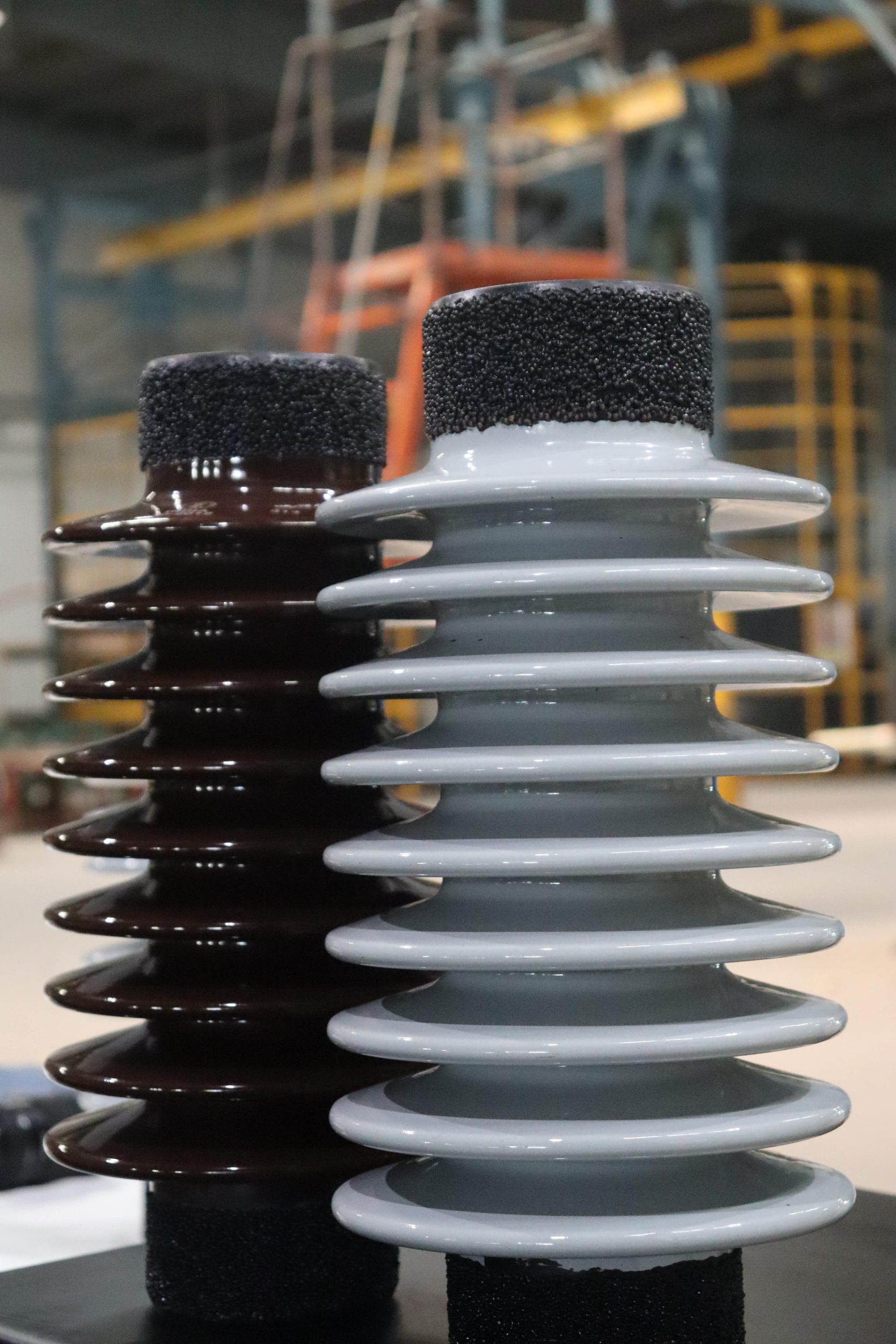
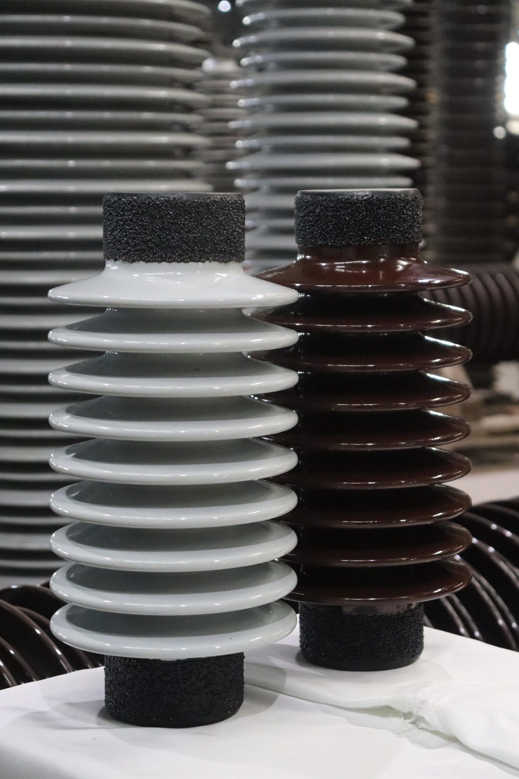
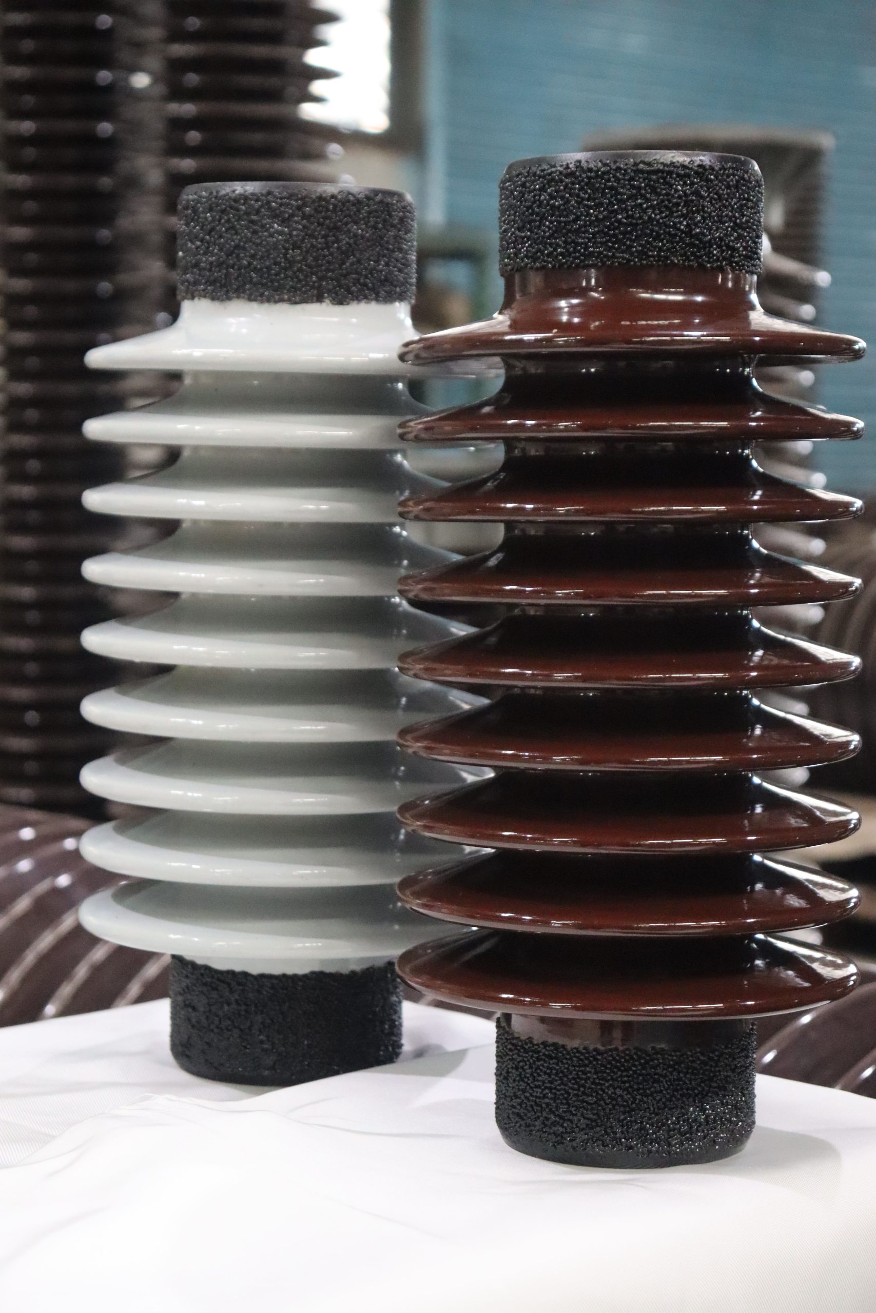
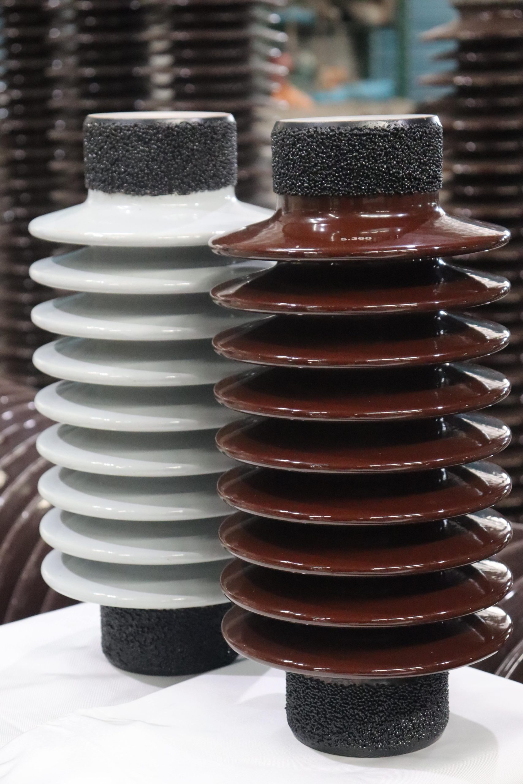
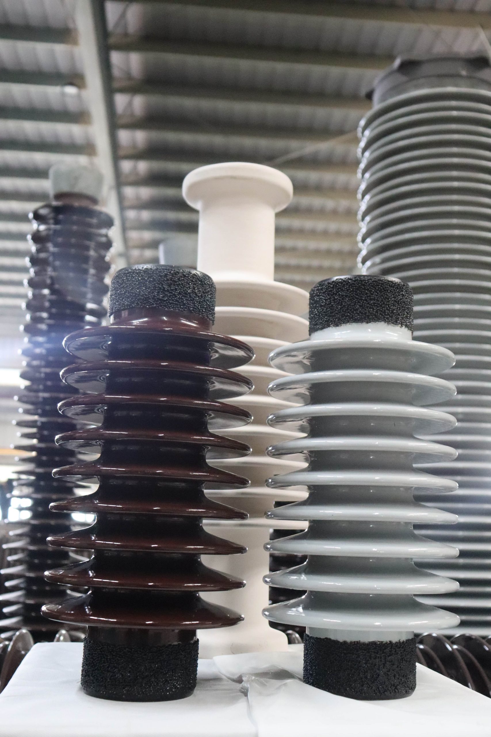
- ANSI SolidCore Post Insulators
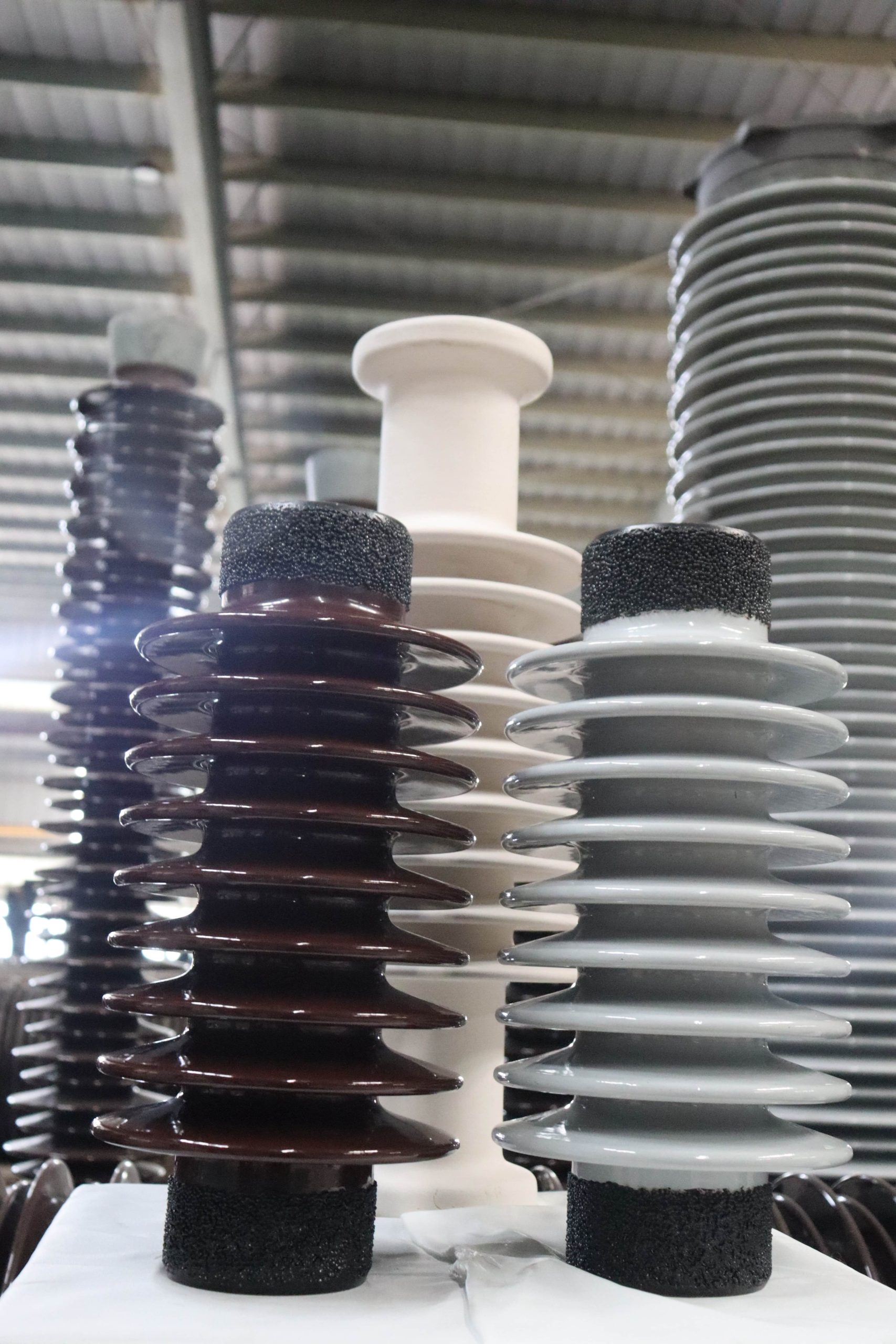
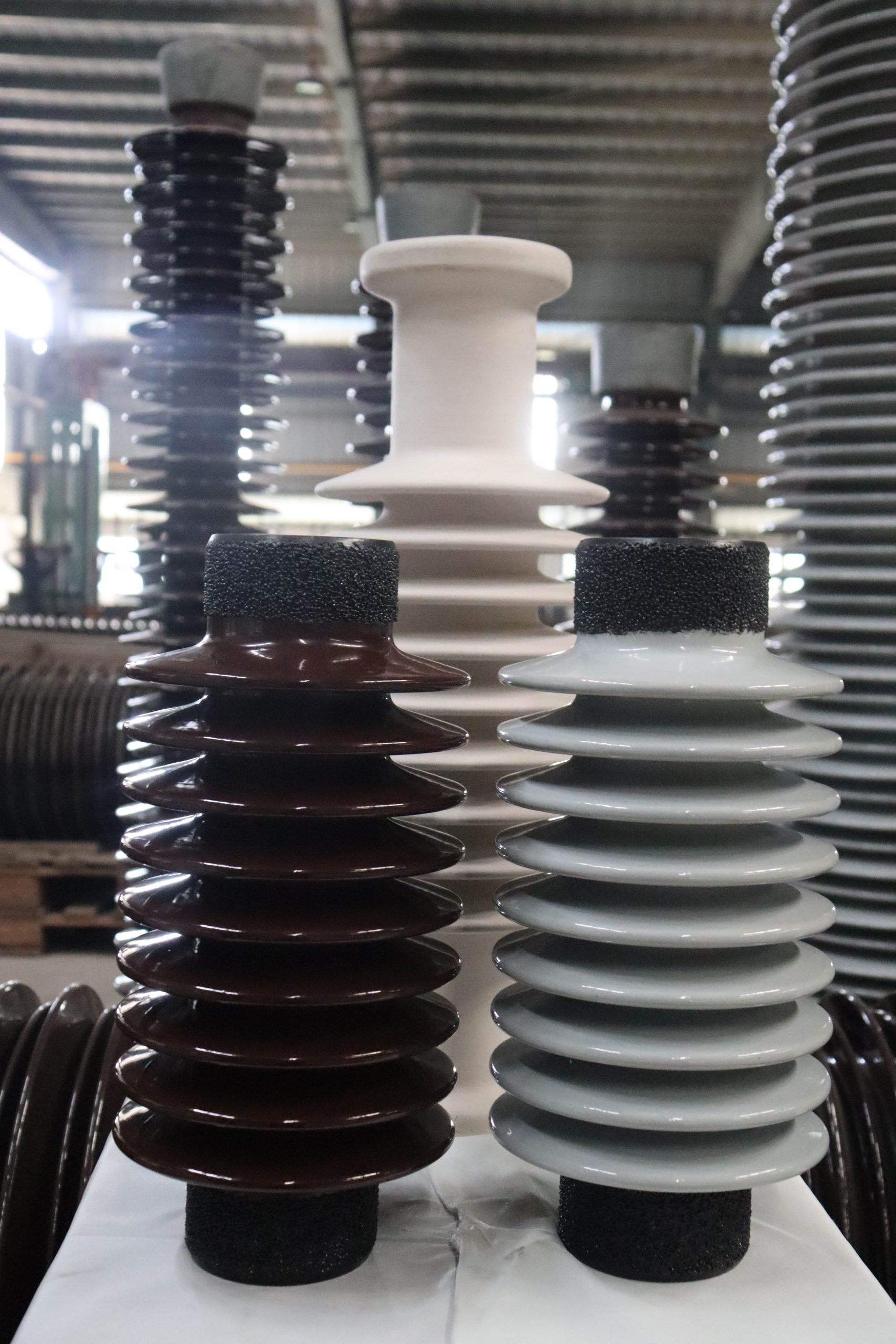
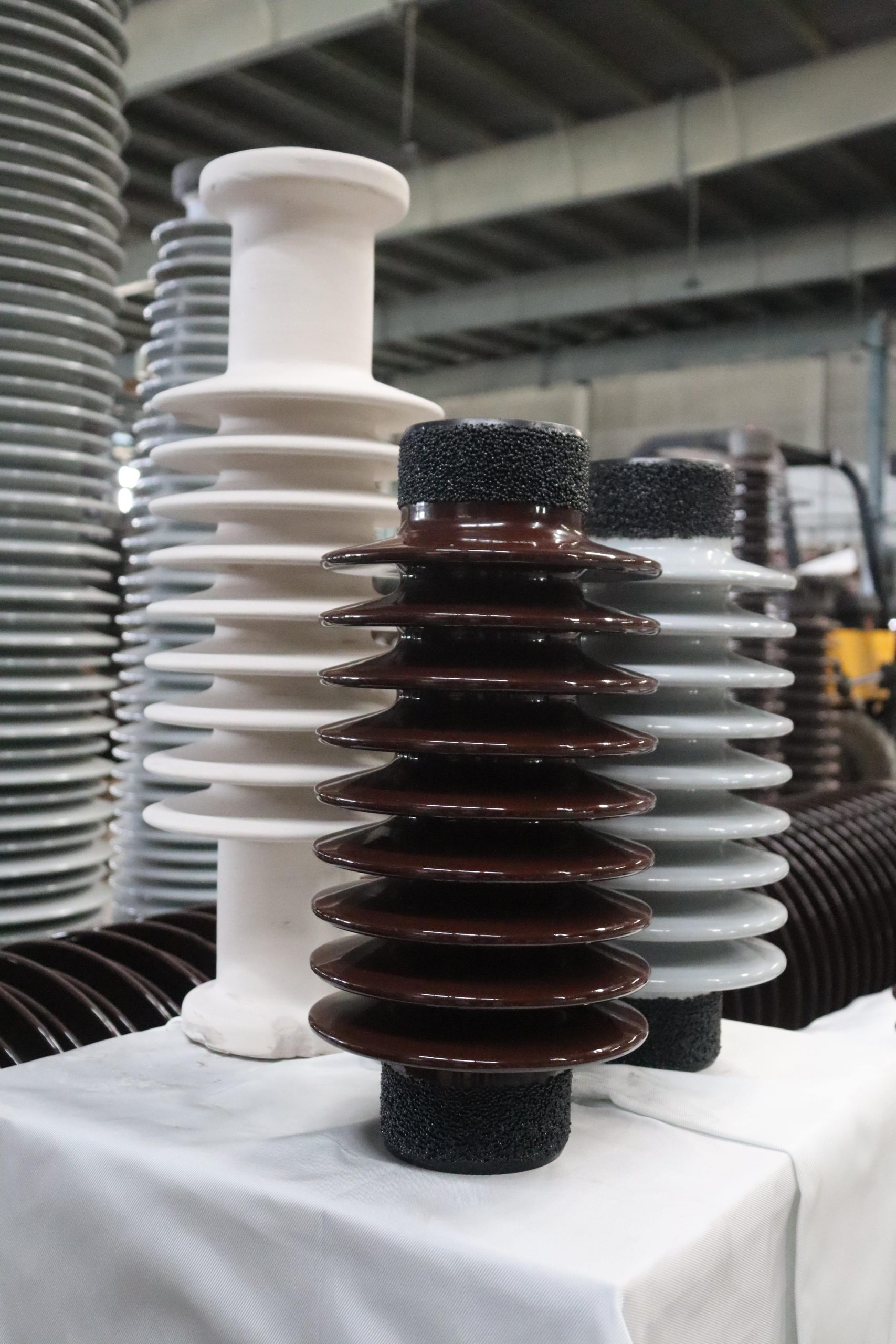
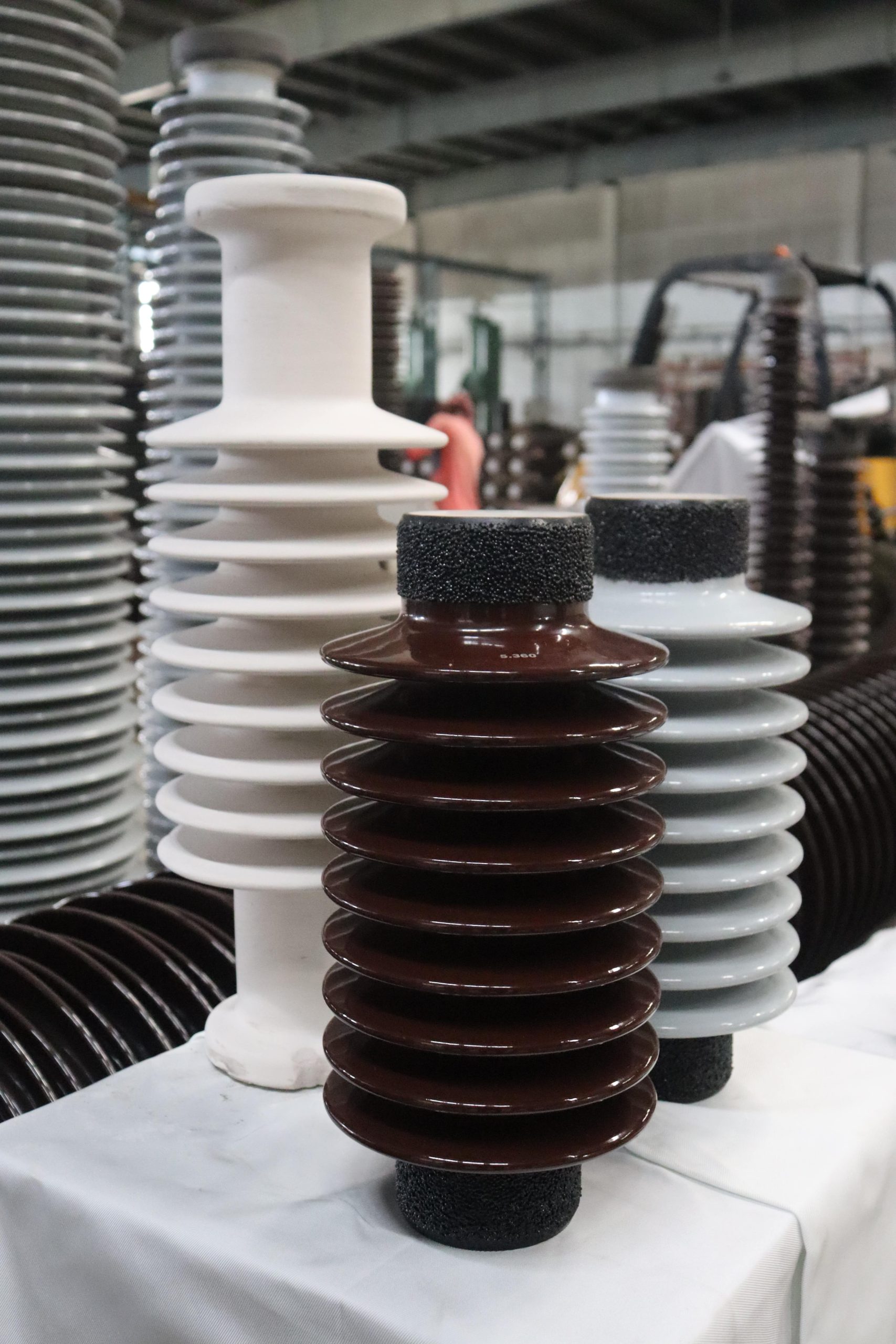
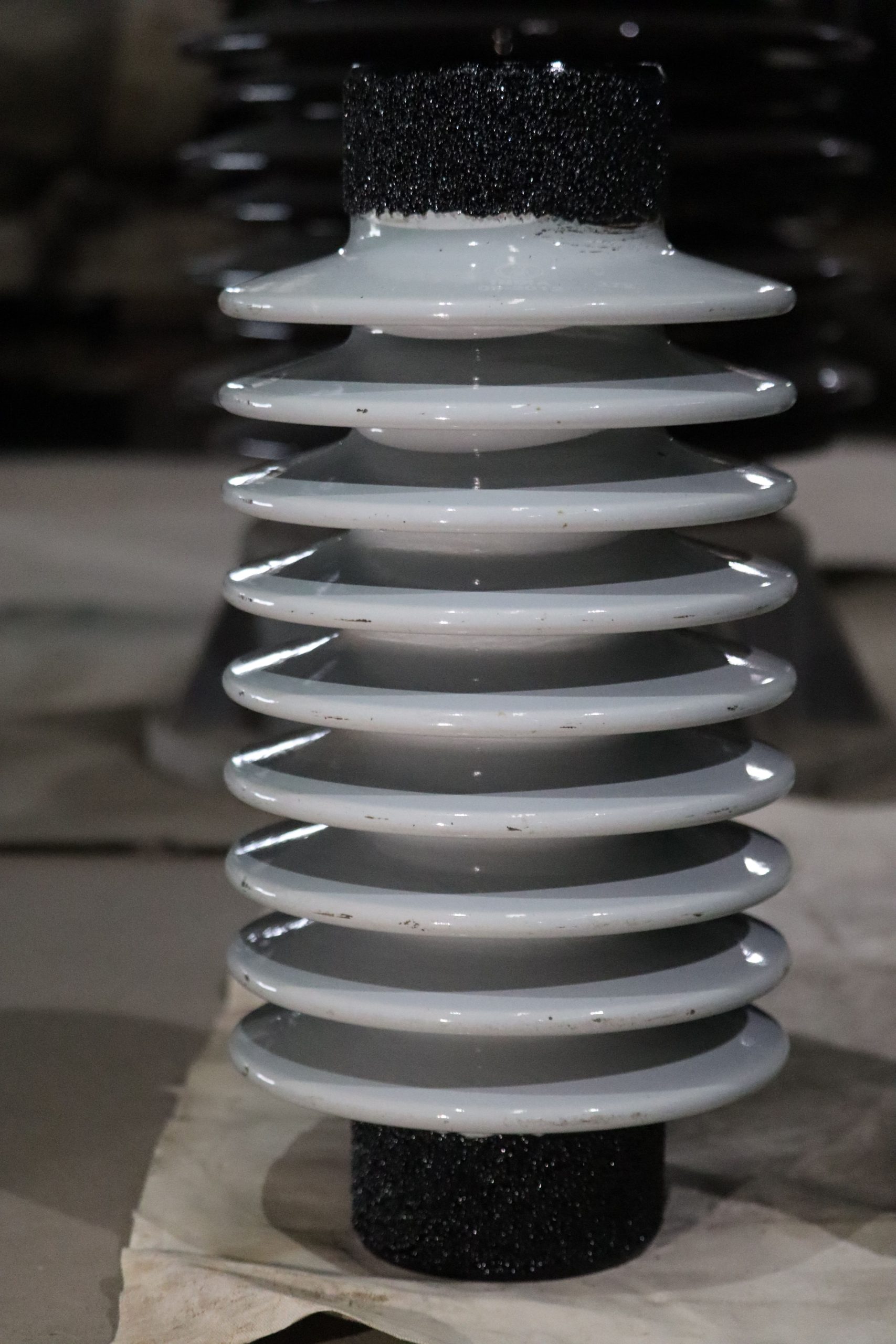
ANSI SolidCore Post Insulators
Welcome to WINWIN Speciality Insulators (WSI), India’s premier ceramic insulator manufacturer. Our commitment to excellence drives us to produce a wide range of high voltage insulators tailored for Power Generation, Substation, Transmission, and distribution systems. And now, WSI is embarking on a new venture to develop Lab Ceramic Utilities designed for diverse laboratory applications.
Our Lab Ceramic Utilities are constructed using high-strength alumina bodies in accordance with IEC 60672 standards. At WSI, we pride ourselves on our cutting-edge equipment for both manufacturing and testing, ensuring the highest quality for our products. Our team comprises skilled experts in Ceramic Lab, Design, and Manufacturing processes, and our seasoned sales professionals stand ready to provide unparalleled customer support at all times.
Our Diverse Applications
spanning from 95 kV (peak) to an impressive 2050 kV (peak). These insulators are engineered to meet the most demanding BIL requirements, ensuring robust performance in even the highest BIL applications.
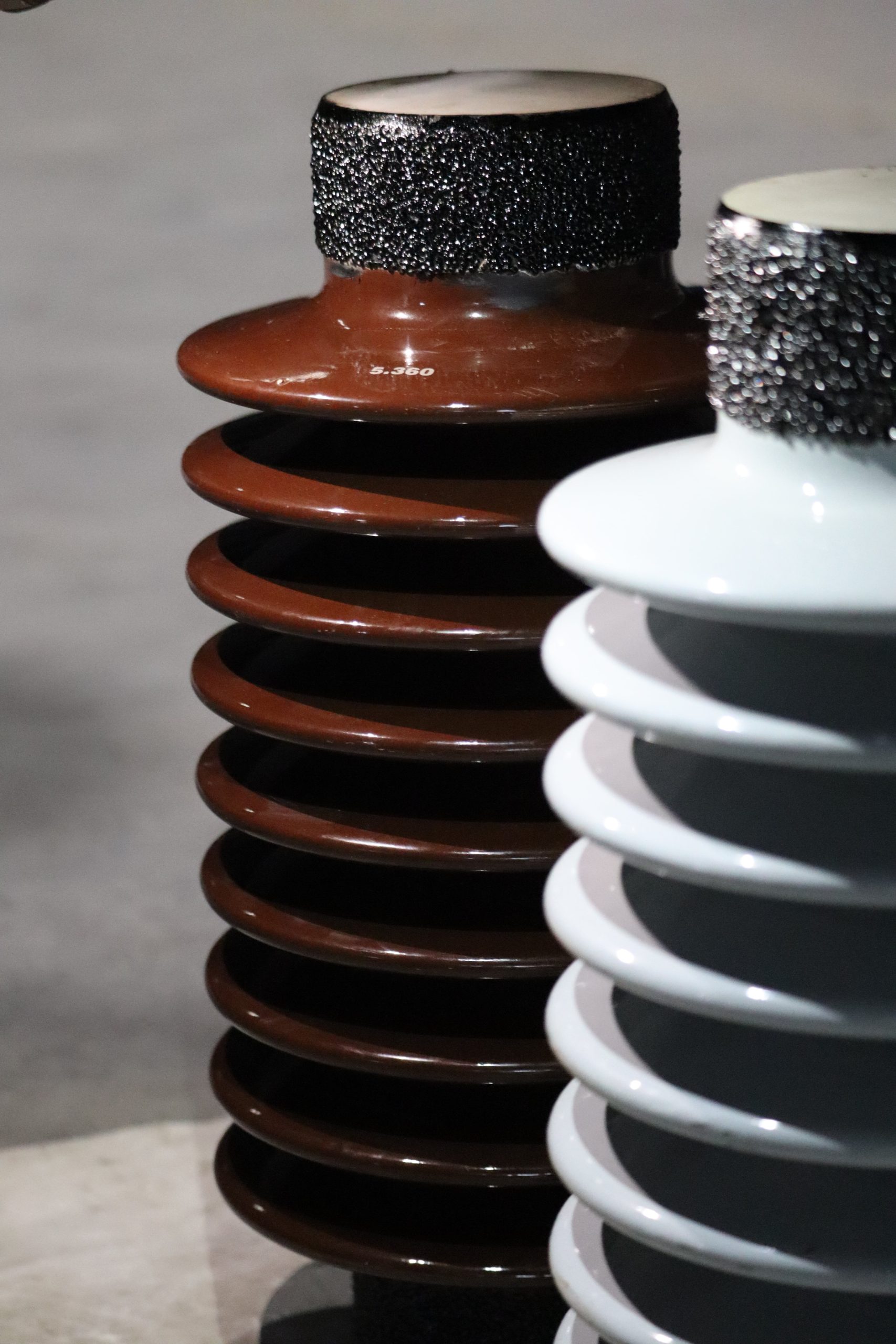
Unmatched Material Quality
Diameter Strength
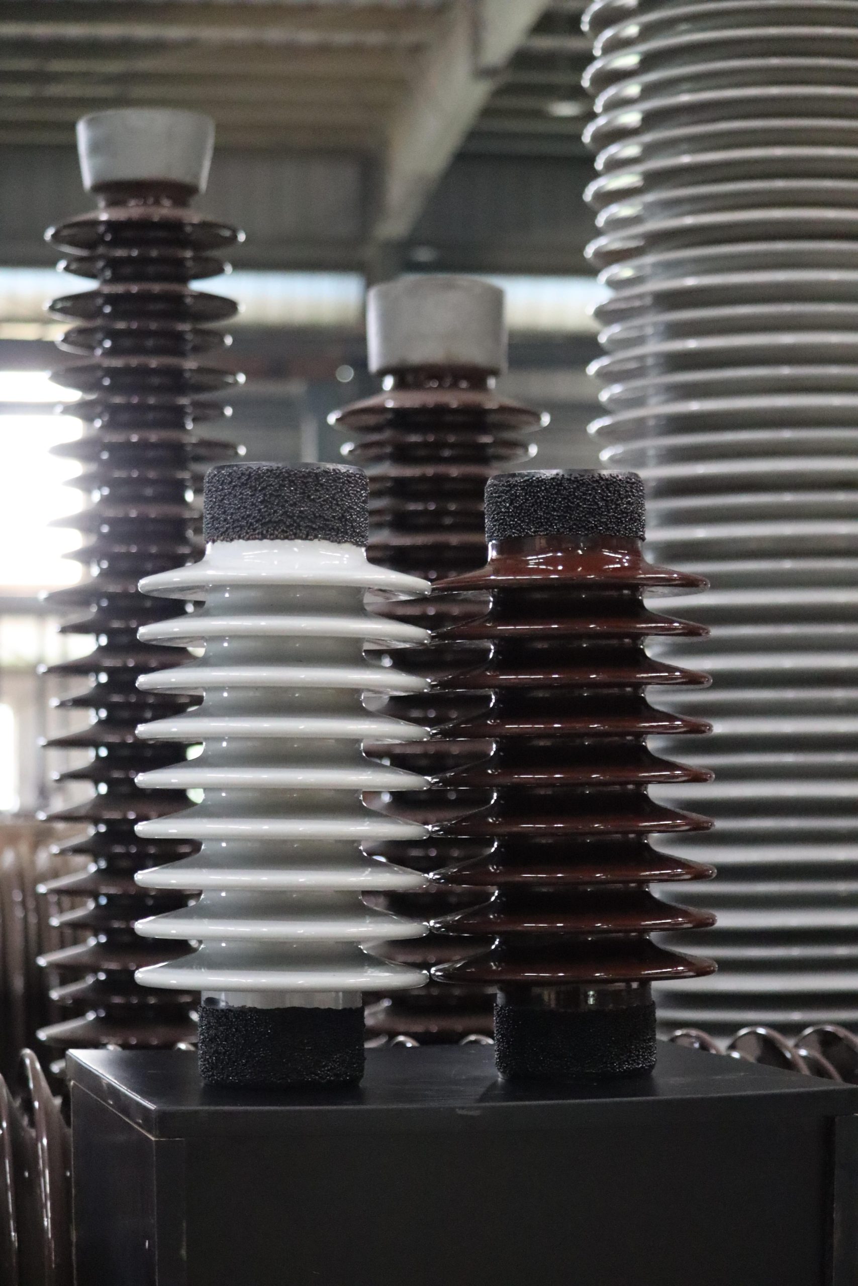
Height and Diameter Flexibility for Your Unique Needs
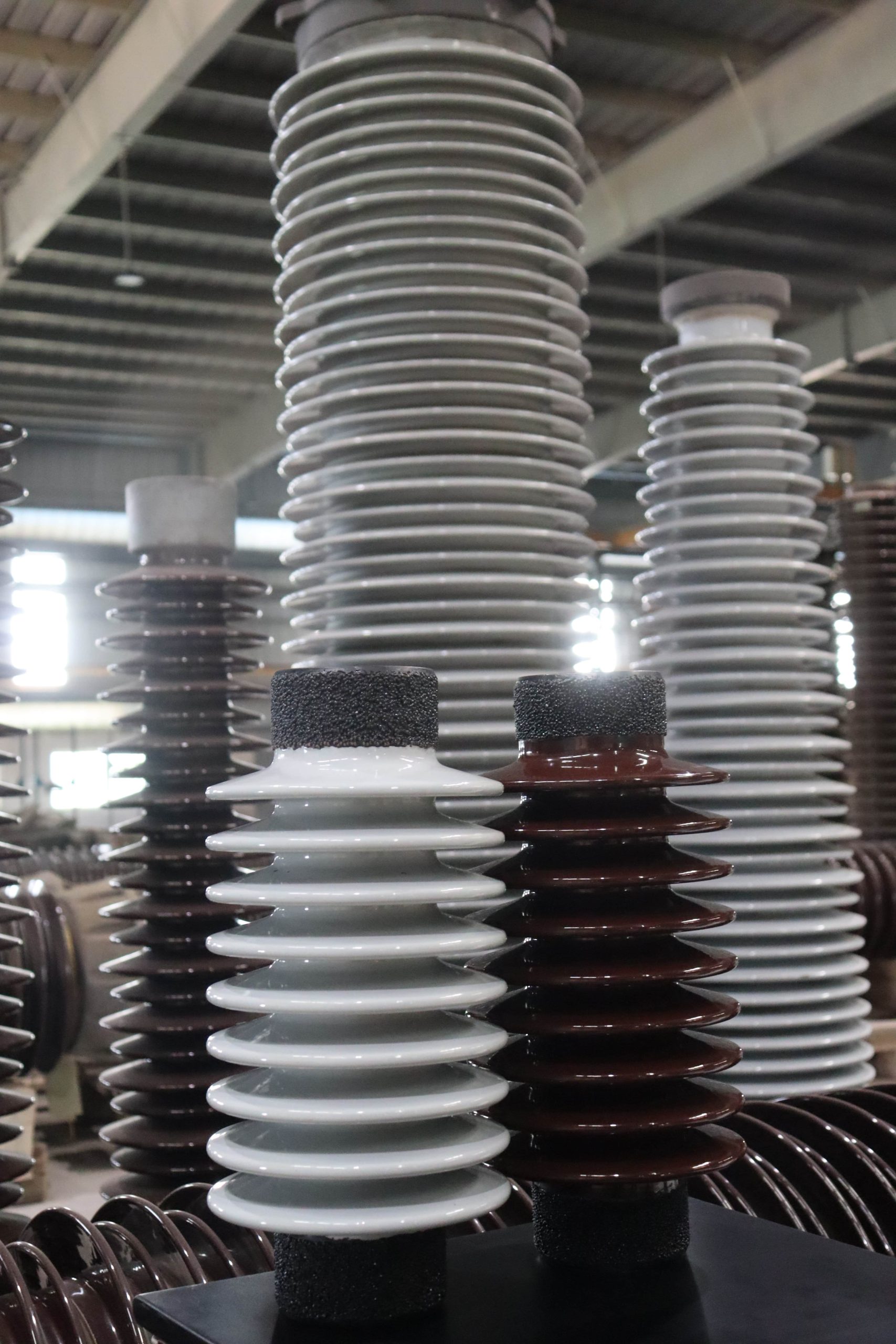
Height Versatility
Versatile Range for Varied Applications
Stringent Quality Assurance
WS ANSI Solidcore Post Insulators Range
-
ANSI SOLIDCORE POST INSULATORS 95 BIL to 350 BIL
- ANSI SOLIDCORE POST INSULATORS 110 BIL to 650 BIL
- ANSI SOLIDCORE POST INSULATORS 900 BIL

| ANSI Reference Number | Units | TR 202 | TR 205 | TR 208 | TR 210 | TR 214 | TR 216 |
|---|---|---|---|---|---|---|---|
| Cantilever Strength (upright) | lbs | 2000 | 2000 | 2000 | 2000 | 2000 | 1500 |
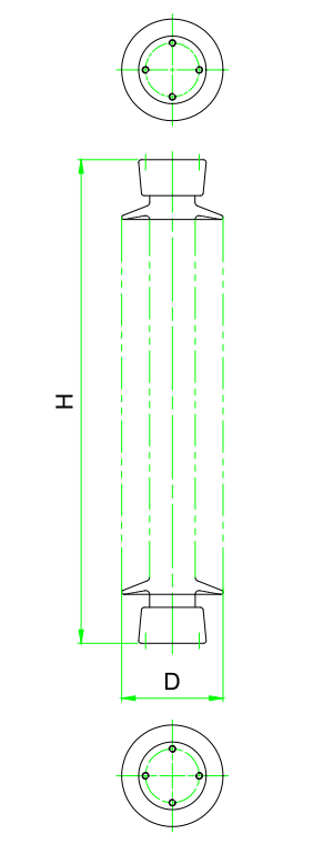
| Total Height (H) | inch (mm) | 7.5 (191) | 10 (254) | 14 (356) | 18 (459) | 22 (559) | 30 (762) |
| Max. Diameter of Insulating Part (D) | inch (mm) | 7 (178) | 7 (178) | 7 (178) | 7.5 (191) | 8 (203) | 9 (230) |
| Top Metal Part Diameter | inch (mm) | 4.3 (108) | 5 (127) | 5.3 (135) | 5.9 (150) | 5.25 (134) | 6.2 (158) |
| Bottom Metal Part Diameter | inch (mm) | 4.3 (108) | 5 (127) | 5.3 (135) | 5.9 (150) | 5.25 (134) | 6.2 (158) |
| Top Pitch Circle Diameter | inch (mm) | 3 (76) | 3 (76) | 3 (76) | 3 (76) | 3 (76) | 3 (76) |
| Number of Holes and Hole dia. | - | 4 x 1/2" | 4 x 1/2" | 4 x 1/2" | 4 x 1/2" | 4 x 1/2" | 4 x 1/2" |
| Bottom Pitch Circle Diameter | inch (mm) | 3 (76) | 3 (76) | 3 (76) | 3 (76) | 3 (76) | 3 (76) |
| Number of Holes and Hole dia. | - | 4 x 1/2" | 4 x 1/2" | 4 x 1/2" | 4 x 1/2" | 4 x 1/2" | 4 x 1/2" |
| Total Creepage Distance | inch (mm) | 10.5 (267) | 15.5 (395) | 24 (610) | 37 (940) | 43 (1092) | 72 (1830) |
| Dry Power Frequency Withstand Voltage | kV | 35 | 50 | 65 | 85 | 115 | 155 |
| Wet Power Frequency Withstand Voltage | kV | 30 | 45 | 60 | 80 | 100 | 145 |
| Impulse Withstand Voltage Positive | kVp | 95 | 110 | 150 | 200 | 250 | 350 |
| Impulse Withstand Voltage Negative | kVp | 95 | 110 | 150 | 200 | 250 | 350 |
| Dry Power Frequency Flashover Voltage | kV | 40 | 55 | 70 | 90 | 120 | 165 |
| Wet Power Frequency Flashover Voltage | kV | 35 | 50 | 65 | 85 | 110 | 155 |
| Impulse Flashover Voltage Positive | kVp | 105 | 125 | 175 | 225 | 280 | 390 |
| Impulse Flashover Voltage Negative | kVp | 115 | 135 | 180 | 235 | 295 | 405 |
| RIV Test Voltage | kV | 5 | 10 | 15 | 22 | 30 | 44 |
| Maximum RIV | ?V | 50 | 50 | 100 | 100 | 200 | 200 |
| Visible Discharge Voltage | kV | 5 | 10 | 15 | 22 | 30 | 44 |
| Cantilever Strength (upright) | lbs | 2000 | 2000 | 2000 | 2000 | 2000 | 1500 |
| Tensile Strength | lbs | 7000 | 8500 | 10000 | 12000 | 14000 | 16000 |
| Torsion Strength | inch-lbs | 6000 | 7000 | 8000 | 10000 | 12000 | 15000 |
| Compression Strength | lbs | 10000 | 10000 | 10000 | 15000 | 15000 | 25000 |
| Weight (approximate) | kg | 6.5 | 9.8 | 15.1 | 21.1 | 23.5 | 41 |
| ANSI Reference Number | Units | TR 225 | TR 231 | TR 278 | TR 286 | TR 288 |
|---|---|---|---|---|---|---|
| Cantilever Strength (upright) | lbs | 4000 | 4000 | 3000 | 1700 | 1400 |
| Total Height (H) | inch (mm) | 12 (305) | 20 (508) | 30 (762) | 45 (1143) | 54 (1372) |
| Max. Diameter of Insulating Part (D) | inch (mm) | 7.5 (191) | 9.1 (231) | 9.5 (240) | 8.85 (225) | 9.65 (245) |
| Top Metal Part Diameter | inch (mm) | 6.3 (160) | 6.3 (160) | 6.9 (175) | 6.3 (160) | 6.9 (175) |
| Bottom Metal Part Diameter | inch (mm) | 6.3 (160) | 6.8 (172) | 6.9 (175) | 6.8 (172) | 6.9 (175) |
| Top Pitch Circle Diameter | inch (mm) | 5 (127) | 5 (127) | 5 (127) | 5 (127) | 5 (127) |
| Number of Holes and Hole dia. | - | 4 x 5/8" | 4 x 5/8" | 4 x 5/8" | 4 x 5/8" | 4 x 5/8" |
| Bottom Pitch Circle Diameter | inch (mm) | 5 (127) | 5 (127) | 5 (127) | 5 (127) | 5 (127) |
| Number of Holes and Hole dia. | - | 4 x 5/8" | 4 x 5/8" | 4 x 5/8" | 4 x 5/8" | 4 x 5/8" |
| Total Creepage Distance | inch (mm) | 15.5 (394) | 37 (940) | 72 (1830) | 100 (2550) | 116 (2946) |
| Dry Power Frequency Withstand Voltage | kV | 50 | 90 | 155 | 245 | 290 |
| Wet Power Frequency Withstand Voltage | kV | 45 | 80 | 145 | 230 | 275 |
| Impulse Withstand Voltage Positive | kVp | 110 | 200 | 350 | 550 | 650 |
| Impulse Withstand Voltage Negative | kVp | 110 | 200 | 350 | 550 | 650 |
| Dry Power Frequency Flashover Voltage | kV | 55 | 95 | 165 | 255 | 305 |
| Wet Power Frequency Flashover Voltage | kV | 50 | 85 | 155 | 240 | 290 |
| Impulse Flashover Voltage Positive | kVp | 125 | 225 | 390 | 610 | 710 |
| Impulse Flashover Voltage Negative | kVp | 130 | 235 | 405 | 630 | 730 |
| RIV Test Voltage | kV | 10 | 22 | 44 | 73 | 88 |
| Maximum RIV | ?V | 50 | 100 | 200 | 200 | 200 |
| Visible Discharge Voltage | kV | 10 | 22 | 44 | 73 | 88 |
| Cantilever Strength (upright) | lbs | 4000 | 4000 | 3000 | 1700 | 1400 |
| Tensile Strength | lbs | 20000 | 25000 | 25000 | 20000 | 20000 |
| Torsion Strength | inch-lbs | 14000 | 20000 | 40000 | 40000 | 40000 |
| Compression Strength | lbs | 20000 | 30000 | 60000 | 60000 | 60000 |
| Weight (approximate) | kg | 16.5 | 28 | 47.5 | 57 | 88 |

| ANSI Reference Number | Units | TR 304 | TR 308 |
|---|---|---|---|
| Cantilever Strength (upright) | lbs | 950 | 1450 |
| Total Height (H) | inch (mm) | 80 (2032) | 80 (2032) |
| Max. Diameter of Insulating Part (D) | inch (mm) | 8.2 (208) | 10.6 (270) |
| Top Metal Part Diameter | inch (mm) | 6.3 (160) | 6.9 (175) |
| Bottom Metal Part Diameter | inch (mm) | 6.8 (172) | 6.9 (175) |
| Top Pitch Circle Diameter | inch (mm) | 5 (127) | 5 (127) |
| Number of Holes and Hole dia. | - | 4 x 5/8" | 4 x 5/8" |
| Bottom Pitch Circle Diameter | inch (mm) | 5 (127) | 5 (127) |
| Number of Holes and Hole dia. | - | 4 x 5/8" | 4 x 5/8" |
| Total Creepage Distance | inch (mm) | 168 (4270) | 165(4191) |
| Dry Power Frequency Withstand Voltage | kV | 405 | 405 |
| Wet Power Frequency Withstand Voltage | kV | 385 | 385 |
| Impulse Withstand Voltage Positive | kVp | 900 | 900 |
| Impulse Withstand Voltage Negative | kVp | 900 | 900 |
| Dry Power Frequency Flashover Voltage | kV | 420 | 420 |
| Wet Power Frequency Flashover Voltage | kV | 400 | 400 |
| Impulse Flashover Voltage Positive | kVp | 1010 | 1010 |
| Impulse Flashover Voltage Negative | kVp | 1030 | 1030 |
| RIV Test Voltage | kV | 146 | 146 |
| Maximum RIV | ?V | 500 | 500 |
| Visible Discharge Voltage | kV | 146 | 146 |
| Cantilever Strength (upright) | lbs | 950 | 1450 |
| Tensile Strength | lbs | 20000 | 25000 |
| Torsion Strength | inch-lbs | 40000 | 90000 |
| Compression Strength | lbs | 60000 | 75000 |
| Weight (approximate) | kg | 94 | 174 |